Ken Cox
StairMaster Wheelchair Co., 2205 Del Ray CT., Arlington, TX 76013Abstract
StairMaster Wheelchair is developing a stair-climbing wheelchair that will provide greatly improved access for most wheelchair users. The StairMaster Wheelchair is operated by a joy-stick and push buttons. It does not require an assistant or the user to grab handrails for climbing. A prototype has been built and is undergoing development testing. While stair-climbing, step-climbing, steep slope and level operation have been demonstrated, more work is needed before it will be ready for marketing. Widespread acceptance of the StairMaster will enable production rates that will make the StairMaster affordable to most wheelchair users.Goals
The standards for a marketable stair-climbing wheelchair are high. It must provide many wheelchair users with safe, greatly-improved-independent access and be affordable. To accommodate most users the wheelchair must accommodate a range of users from those with minimal strengths and control to those who just need a little help on stairs. It also must support their daily needs for transfers, approaching tables, reclining etc. To be safe, the wheelchair must forgive operator errors, and be able to halt safely if needed. It must be fully analyzed, tested, and every effort made to ensure it is safe and feels safe. A stair-climbing wheelchair is an FDA class III medical device and must receive FDA premarket approval before it can be sold. To improve access, it must accommodate a wide range of architectural barriers, including steps or curbs to 9.5" high, indoor stairs to 42º, slopes to 20º, narrow doorways, narrow hallways, sand, grass, and gravel. It must provide the access without the aid of an assistant or handrails.
The stairmaster wheelchair
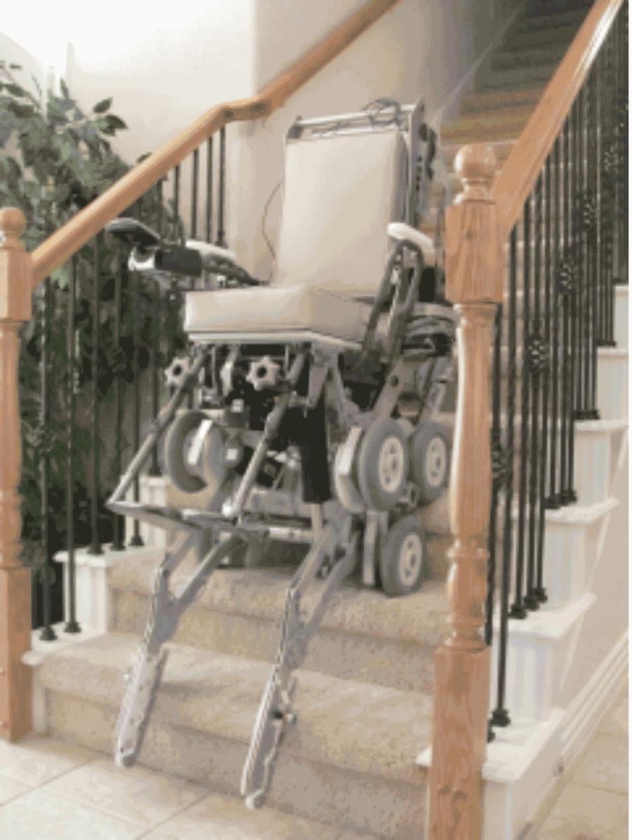 Figure 1 - StairMaster on Stairs
The wheelchair is shown in Figures 1, 3, and 4 on stairs and in the level mode on Figure 2. It can turnaround in a small area with the leg rest in the most aft position. The chair is 21-3/4” wide and will climb 42-degree stairs and 18-degree slopes. Operation on level ground is similar to that of a conventional wheelchair.
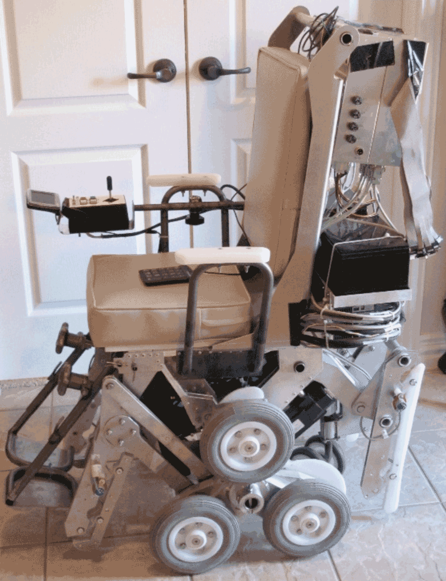 Figure 2 - Level Position
 The stair-climber provides 18” between the armrests. It is supported by a dual-tire retractable rear caster and by two spider wheels mounted to the sides. The spider wheels provide propulsion for stair-climbing, slope-climbing and level operations. Retractable skids are mounted to the forward front corners to provide stability when stair and slope-climbing. The rear minor wheels stay off the ground in level operations to avoid tire scrubbing.
The turning center for level operations is between the two forward supporting minor wheels. The rear caster retracts for stair- climbing. When the chair is converted from stair mode to level mode, the spider wheels are locked by spring-loaded motor brakes, and caster deployment lifts the aft minor wheels off the ground. The front and rear skids are adjusted to level the chair during stair-climbing. Front skids are retracted in level mode.
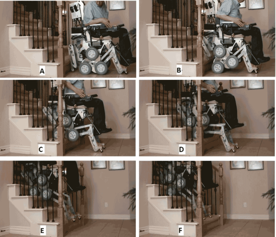 Figure 3 - Climbing Stairs
 The wheelchair has load-bearing removable armrests. Seat and back rest are foam cushions. The chair has a seat cushion height of 20” above the floor, armrest height of 9”, and back rest height of 28” above the seat. The seat bottom angle is 5º and seat back angle is 80º. Individually adjustable footrests are mounted on telescoping struts to provide vertical extension. The footrest struts are hinged at the top to provide fore and aft adjustments. The footrests are positioned aft to enable turning on a small stair landing. A raised position is provided for forward support of the legs if desired. The footrests may be moved aft for approaching a bathtub.
Friction in the acme screw actuators and spring-operated brakes on the propulsion and spider motors lock the wheelchair in place when it is stopped on the stairs at any position. Spider wheels engage the stairs to propel and stabilize the chair during climbing and descending. A large percentage of the weight is carried by the spider wheels for climbing. Propulsion and transition control power are provided by individual DC motors and acme screw actuator systems. Propulsion for both level operation and stair climbing is supplied by the same DC motors and transmitted through the same spider wheels and minor wheels.
Figure 3 shows the StairMaster climbing a home carpeted stairway. All axes are locked for safety and stability at all instances when the chair is not in powered motion up or down the stairs. This prevents the chair from moving or tipping when it’s stopped on the stairs regardless of the driver's position, including when the driver’s torso is resting in his or her lap or when the driver is reaching behind the chair. Control of the wheelchair’s five axes is provided by a computer. The driver selects the mode with push buttons and the speed and direction with a joy stick. The computer does the rest.
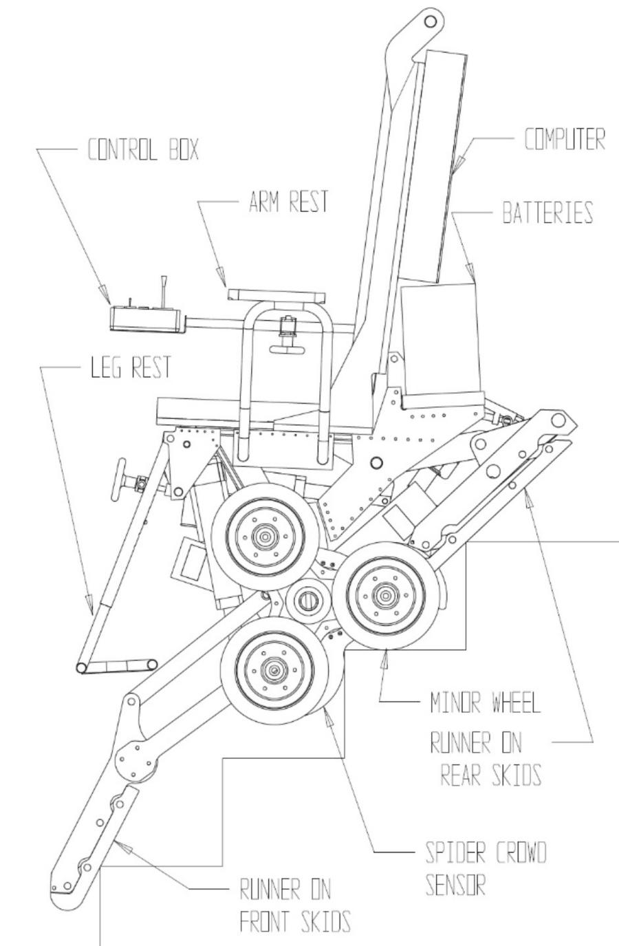 Figure 4 - Side View of Wheelchair on Stairs
 The wheelchair driver faces down the stairs during both ascending and descending operations. A backup camera and monitor aid steering in reverse for stair and slope-climbing. To climb stairs the driver backs the wheelchair near the stairs and then selects stair mode. When the chair is backed, the spider is rotated to control pitch. The caster and front skids are held in close proximity to the floor or stairs. When the rear skids contact the first stair riser (Figure 3A) the rear skids are then raised as required to keep them close to the stairs but not firmly loaded against the riser. This continues as long as the joystick is deflected. At this point the caster is lifted off the floor, a spring loaded roller and cam center the caster wheels in either the backing or advancing direction.
When the spider is crowded against the stair riser as shown in Figure 3B, spider rotation is begun. Meanwhile, front and rear skids are moved as required to level the chair and keep both either balancing or lightly contacting the stairs or floor. In Figure 3C a minor wheel reaches the tread of the first step. At this point, the chair also backs as required to keep the spider wheels close to the stair riser. The spider cams steer the chair to keep both sides close.
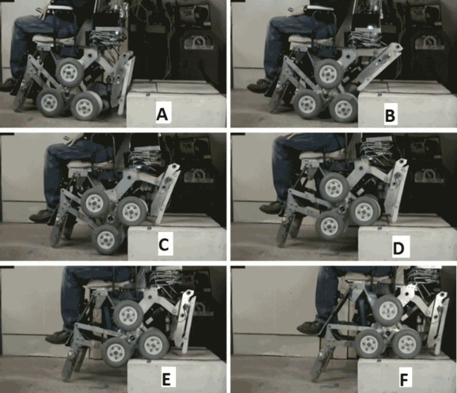 Figure 5 - Wheelchair Climbing an 8" Step
 At Figure 3D, the spiders have rotated and backed so that they are crowded against the riser of the second step. Ascending continues in the same manner in Figure 3E & F to the top step until the caster and two minor wheels of each spider are resting on the top landing. In the event that the chair pitch attitude should exceed a normal operating range, all motion stops until the pitch is corrected. Meanwhile the front skids continue to track closely to the stairs. Selecting the level mode is not permitted by the computer until the front skids reach the top landing or first step down. At this point level mode is selected and the chair can turn on the stair landing, if needed. The wheelchair descends the stairs in a manner similar to ascending, reversing Figure 3F through Figure 3A.
Figure 5 shows the wheelchair climbing an 8” step. Notice the lifting of the rear skids and caster and the front support by the skids.
pricing
Characteristics |
StairMaster-Production Version |
|---|---|
Required User Capabilities |
Able to dial a phone |
Max Passenger weight |
220 lbs |
Width |
21.5” at arm rest |
Length |
42" including feet |
Ground Clearance |
2.9'’ |
Caster wheels |
5” solid |
Wheels |
8” foam filled |
Controller mount |
Swing away controller |
Arm rest |
Swing up |
Max Level speed |
3 miles per hour |
Battery life distance |
12 miles |
Max level mode slope |
6º |
Max step/ curb height-advance down/back up |
0 to 5.0” steps |
Max step/ curb height advance up/back down |
0 to 1.5” steps |
Max 4-wheel slope |
21º |
4-wheel mode |
yes |
Stair slope |
42° max (i.e. 9" tread x 8" riser) |
Stair/Step mode |
3.5 to 9.5” |
hand rails required |
no |
Seat lift |
0 to 2.5" |
Recline (Tilt) |
5 to 28º seat bottom |
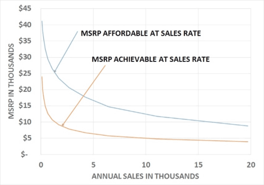 Figure 6 - Affordable vs. Achievable Selling Price
 The StairMaster can’t be successful, if the ones who could use it can’t afford it. We can’t set a firm price without knowing the production quantities, and seeking bids and pricing all of the components and efforts needed to get the wheelchair to the end user. But we can estimate the price. We can estimate the number persons who would buy it based on a low percentage of the number of persons who have difficulty climbing stairs and their level of income from TABLE 1 in “Demographics and Trends in Wheeled Mobility Equipment Use and Accessibility in the Community”1. We assume they could pay a certain percent of their income for a wheelchair. That sets the upper limit of MSRP. We then allocate a percentage of the MSRP for customer acquisition, development amortization, fabrication cost, product liability/warrantee and profit. Those numbers will be our targets. See Figure 6 - Affordable vs. Achievable Selling Price. It clearly shows a real benefit to getting the quantity up and the price down. Sales could be 10,000 per year if the selling price were $12,500 or 20,000 per year if the price were $9,000. Then the question is can we get the price down to meet those targets by manufacturing in production quantities? We then estimate the MSRP using curve fitting from cost per pound for the original prototype to cost per pound data and production rate for automobiles. See the MSRP ACHIEVABLE AT SALES RATE curve for the production quantities required to get the price down. The margin between these curves gives hope that a selling price can be achieved that customers can afford. Test marketing will likely start at the higher price and lower rate. Prices will come down as sales quantities increase. Caution: These numbers are based on assumptions which may not be accurate. The trend is likely more valid than the actual numbers.
Production Stairmaster
The production StairMaster will include features to support user’s daily needs, including transfers, recline, table approach, and tight spaces. It will also be suitable for outdoor use including speeds, distances, all terrain and home egress. See Table 1 - StairMaster Characteristics for a listing of planned characteristics. They are subject to change. See also the StairMaster patent2 for more information.
References
- Demographics and Trends in Wheeled Mobility Equipment Use and Accessibility in the Community, from Assistive Technology®, 22:3–17, 2010, Mitchell P. LaPlante, PhD, and H. Stephen Kaye, PhD
- Battery Powered Stair-Climbing Wheelchair; US Patent 6,484,829, November 26, 2002
Audio Version PDF Version